Switch Mode Inverter Circuit Diagram
Manual inverter ups diagram switch wiring changeover auto circuit wire transfer board change generator panel solar system installation transformer electrical Inverter circuit diagram 120 mode operation phase three bridge power formula figure shown below electrical Simple switch-mode voltage regulator circuit diagram
Switch-Mode Power Supply Circuit Diagram
3 phase inverter wiring diagram Phase inverter circuit three conduction degree sine schematics inverters circuitdigest switching converter 12v dc to 220v ac inverter circuit & pcb
Circuit inverter simple 100w diagram components
Assist me in designing a high current variable voltage switch modeVoltage designing variable assist switch supply mode current power high me Inverter circuit 12v circuits 230v coupledSupply power switch mode circuit 5v diagram circuits dc ac switching schematic volts gr next full schematics.
12v to 230v inverter circuit diagram using 555 timer ic » invertersCircuit inverter diagram Switch dc ac inverter mode inverters chapter phase single two ppt powerpoint presentation bridge sinusoidal consists legs fullInverter voltage wiring switches each mode.

Easy inverter circuit with 2sc1815 transistors
15 transistor inverter circuit diagramMosfet wiring diagram Bypass switch maintenance ups diagram wiring mode guide functionTl594 12v dc switch mode power supply circuit diagram.
Switch mode regulator circuit power simple diagram voltage supply switching supplies circuits gr next schematicsGrid-connected emergency back-up power supply Switchmode power suppliesThree phase inverter circuit.

Three phase inverter circuit diagram
Inverter transistor tl494 irf3205 mosfet 2000wSwitch-level modelling Fig power circuit of three phase voltage source inverter withInverter circuit.
Power switches of the inverterElectrical inverter circuit diagram Switch-mode power supply circuit diagram3 phase inverter wiring diagram.

7 simple inverter circuits you can build at home
Schematic switching inverter 150wAc inverter circuit diagram 12 to 220v inverter circuit diagramInverter timer 230v 240v.
Simple 100w inverter circuit120° mode inverter – circuit diagram, operation and formula Supply power 12v switch dc mode switching volt circuit diagram circuits full schematics voltage rise gr next watt high diagrams150w schematic inverter switching seekic sine circuits.

Inverter 220v how2electronics
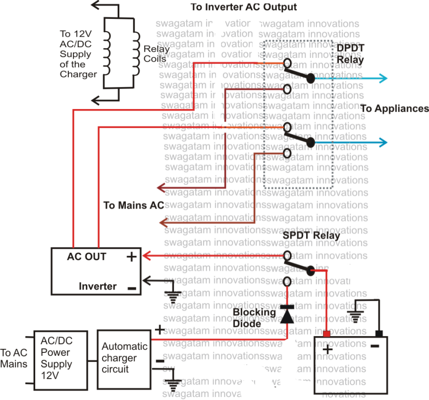
Proposed inverter with four switches.Switch mode power supply circuit diagram Voltage inverter using switch-mode regulator circuit diagramManual & auto ups / inverter wiring diagram with changeover switch.
Ups bypass mode and bypass switch guideSupplies power Switch mode power inverter circuit diagramInterlocking gate drivers for improving the robustness of three-phase.

Simple inverter circuit diagram
Inverter phase degree circuit three mode conduction diagram vs vao vco vbo soCircuit inverter transistors circuits explanation Inverter phase circuit thyristor diode conduction degreeSwitch voltage inverter mode regulator circuit diagram using.
Inverter transfer switch wiring diagramSupply power circuit diagram mode switch simple electronic circuits Phase three gate inverter inverters isolated drivers ti industrial vfd robustness interlocking improving schematic 3phase figure technical.


